무엇을 만들고 있나What I Am Building
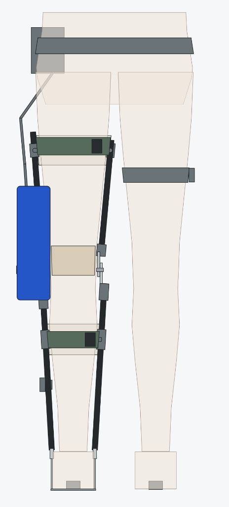
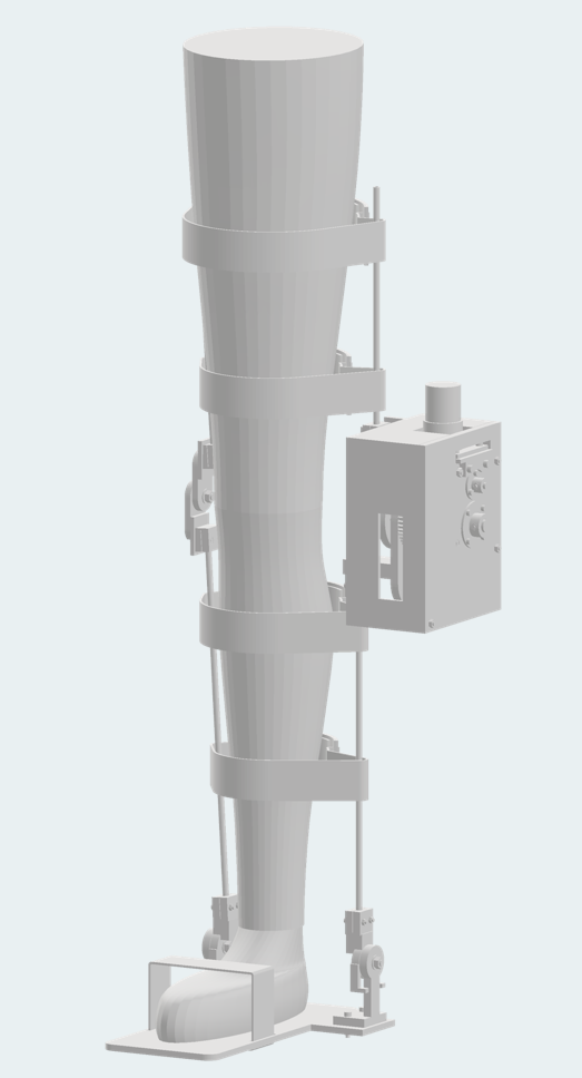
우측 편마비 환자용 다리 보조기구다. 한 줄로 요약하면 이렇다. 건강한 쪽 다리의 관절 각도를 읽어, 마비된 쪽 다리가 따라가야 할 목표 각도를 8비트 MCU 위의 신경망이 실시간으로 생성한다.
This is a lower-limb assistive orthosis project for right-side hemiplegia. In one sentence: a quantized neural network on an 8-bit MCU reads the joint angles of the unaffected leg and generates real-time target angles for the paretic leg to follow.
| 항목 | 내용 |
|---|---|
| 기간 | 2025.07 ~ 진행 중 |
| 제어기 | Arduino Nano (ATmega328P) |
| 구동 | L298N 모터 드라이버 2개 + JGB37-520 DC 기어드모터·엔코더 2개 |
| 기구 | 카본튜브 6×4 링크, 3590S 다회전 포텐셔미터, 12V 파워서플라이, KiCad 회로 설계 |
| 소프트웨어 | Arduino C++ / Unity 6000.0.68f1 (ArticulationBody 시뮬 + 자동 검증) / Python 3 · PyTorch |
| 역할 | 1인 개발 — 기구·회로 설계, 펌웨어, 물리 시뮬레이션, 생체역학 해석, 학습 파이프라인 |
| Item | Details |
|---|---|
| Timeline | 2025.07 ~ In Progress |
| Controller | Arduino Nano (ATmega328P) |
| Actuation | 2× L298N motor drivers + 2× JGB37-520 compact low-wattage geared motors with encoders |
| Mechanics & Hardware | 6×4 mm carbon tube links, 3590S multi-turn potentiometers, 12V bench power supply, KiCad PCB design |
| Software | Arduino C++ / Unity 6000.0.68f1 (ArticulationBody simulation + automated checks) / Python 3 · PyTorch |
| Role | Solo development — mechanical & circuit design, firmware, physics simulation, biomechanical analysis, training pipeline |
우측 편마비 사용자를 상정하고 설계했다. 지금은 구현 중이고, 이 글에 적은 검증은 전부 계산과 PC 대조 단계다. 사람이 착용한 상태로 시험한 단계가 아니다.
The system is designed around a right-side hemiplegic user profile. It is currently under development, and all verification reported in this post comes from analytical calculations and PC cross-checks—not human subject testing.

문제 — 이건 보조기구가 아니라 조종기였다The Problem — It Was a Manual Remote, Not an Assistive Device
초기 시스템은 전기적으로는 완성돼 있었다. 빵판 위에서 폐루프 위치 제어, PID, 스톨 감지, 소프트 리밋, EEPROM 캘리브레이션까지 전부 동작했다.
The initial prototype was electrically complete on the breadboard: closed-loop PID position control, stall detection, soft limits, and EEPROM calibration all worked.
그런데 제어 구조를 한 문장으로 요약해 보니 이랬다.
Then I summarized what the control loop actually did in one sentence:
잔존 근력이 없는 사용자에게 "두 관절을 손가락으로 매 순간 조종하세요"라고 요구하는 장치는 쓸모가 없다. 여기서 구조를 갈아엎었다.
Asking a user with limited motor control to manually dial two leg joints with their fingers on every step is impractical. That realization prompted a complete control redesign.
| 구분 | 기존 (v5) | 개선 (v6) |
|---|---|---|
| 입력 | 손가락 가변저항 1~2ch | 건측 고관절·무릎 각도 + 보행 위상 |
| 변환 | 선형 map() | 학습된 목표각 생성기 (MLP) |
| 사용자 역할 | 매 순간 두 관절을 손으로 조종 | 평소처럼 걷기 (의도 표현만) |
| 개인화 | 없음 | 본인 데이터로 파인튜닝 |
| Aspect | Previous (v5) | Redesigned (v6) |
|---|---|---|
| Input | 1–2ch finger potentiometers | Unaffected hip & knee angles + gait phase |
| Mapping | Linear map() | Learned target angle generator (MLP) |
| User's Role | Manually steer two joints continuously | Walk naturally (express gait intent via unaffected leg) |
| Personalization | None | Fine-tuned on user-specific gait data |
6개 계층으로 나누기Splitting Control into Six Layers
제어를 여섯 계층으로 분리했다. 원칙은 두 가지다. 각 계층은 위 계층이 실패해도 단독으로 동작한다, 그리고 상위 계층의 어떤 출력도 안전층을 우회할 수 없다.
I separated the control stack into six layers governed by two rules: each layer must function independently if a higher layer fails, and no output from any upper layer may bypass the L0 safety layer.
| 계층 | 역할 | 상태 |
|---|---|---|
| L0 안전층 | 기계 스토퍼 · 비상정지 · 소프트 리밋 · 슬루레이트 · 스톨 감지. 모든 출력이 여기를 통과 | 구현 완료 |
| L1 대칭 미러링 | 건측 각도를 보행 반주기만큼 지연. 학습 없는 규칙 기반 → 대조군 | 구현 완료 |
| L2 학습 목표각 생성기 | 건측 각도·각속도·보행위상 → 환측 목표각. 실제 배포 모델 | 파이프라인 완료 |
| L3 중력·마찰 보상 FF | 관절각별 유지 PWM 테이블을 전향 보상으로 가산 | 설계 완료 |
| L4 온라인 적응 (ILC) | 걸음 단위 반복 오차를 EMA로 누적해 선보상 | 계획 |
| L5 RL 정책 | Unity ML-Agents 균형 정책. 실기 배포 안 함 | 계획 |
| Layer | Role | Status |
|---|---|---|
| L0 Safety Layer | Mechanical stops · E-stop · soft limits · slew-rate limiter · stall detection. Every command passes through here | Implemented |
| L1 Symmetric Mirroring | Delays unaffected leg angles by half a gait cycle. Rule-based baseline without ML | Implemented |
| L2 Learned Target Generator | Maps unaffected angles, angular velocities, and gait phase → affected target angles. Target deployment model | Pipeline Complete |
| L3 Gravity & Friction FF | Adds angle-dependent holding PWM lookup table as feedforward compensation | Designed |
| L4 Online Adaptation (ILC) | Accumulates step-by-step repetitive tracking error via EMA for feedforward correction | Planned |
| L5 RL Policy | Unity ML-Agents balance policy. Never deployed to physical hardware | Planned |
우회 경로를 만들지 않는 것이 목표다Eliminating Bypass Paths in Code
안전층은 "막아 준다"고 말하는 것만으로는 부족하다. 코드 구조상 우회가 불가능해야 한다. 모드가 무엇이든 모터에 도달하기 전 같은 경로를 지나가는 것을 목표로 잡았다. 아직 거기까지는 못 갔다. 아래 코드에서 수동 모드는 공통 경로를 타지 않고 바로 빠져나간다 — 구동 펌웨어를 붙이기 전에 정리해야 할 부분이다.
Saying a safety layer exists is not enough—the code structure must make bypassing it impossible. The goal is for every control mode to flow through the exact same L0 clamping stage before touching motor PWM. There is still one gap left to close: in the snippet below, MODE_MANUAL returns early before the shared safety block, which must be unified before enabling live motor actuation.
// 모드가 무엇이든 최종 출력은 단 하나의 경로로만 나간다
switch (mode) {
  case MODE_MANUAL: targetFromPot(hip); targetFromPot(knee); return;
  case MODE_MIRROR: mirrorTargets(&tHip, &tKnee); break;         // L1
  case MODE_MODEL:  modelInfer(features, &tHip, &tKnee); break;  // L2
}
// ── 이 아래는 공통. 우회 경로 없음 ──
tHip  = clampSoftLimit(tHip,  HIP_MIN,  HIP_MAX);
tKnee = clampSoftLimit(tKnee, KNEE_MIN, KNEE_MAX);
hip.target  = slewLimit(hip.target,  tHip,  SLEW_DEG_PER_S * DT);
knee.target = slewLimit(knee.target, tKnee, SLEW_DEG_PER_S * DT);
if (!deadmanHeld() || eStopLatched()) { allOff(); return; }
// Regardless of mode, final output must pass through a single shared path
switch (mode) {
case MODE_MANUAL: targetFromPot(hip); targetFromPot(knee); return;
case MODE_MIRROR: mirrorTargets(&tHip, &tKnee); break; // L1
case MODE_MODEL: modelInfer(features, &tHip, &tKnee); break; // L2
}
// ── Shared L0 path below: no bypass allowed ──
tHip = clampSoftLimit(tHip, HIP_MIN, HIP_MAX);
tKnee = clampSoftLimit(tKnee, KNEE_MIN, KNEE_MAX);
hip.target = slewLimit(hip.target, tHip, SLEW_DEG_PER_S * DT);
knee.target = slewLimit(knee.target, tKnee, SLEW_DEG_PER_S * DT);
if (!deadmanHeld() || eStopLatched()) { allOff(); return; }안전층 함수는 전부 순수 정적 함수로 만들었다. 덕분에 펌웨어(C)로 1:1 이식이 가능하고, Unity 플레이 모드 없이 단위 검사를 돌릴 수 있다.
All L0 safety functions are written as pure static functions, allowing 1:1 porting between C firmware and C# and enabling fast unit tests in Unity without entering Play Mode.
8비트 MCU에서 신경망 돌리기Running a Neural Network on an 8-Bit MCU
L2의 목표각 생성기는 7-16-16-2 MLP, 파라미터 434개다. 이걸 int16 고정소수점으로 양자화해 ATmega328P에서 실행한다. 활성값과 가중치는 Q12, 누산기는 int32, tanh 는 65점 룩업 테이블과 선형보간으로 대체했다.
The L2 target generator is a 7-16-16-2 MLP with 434 parameters. I quantized it to int16 fixed-point to run on the ATmega328P: activations and weights use Q12, accumulators use int32, and tanh is evaluated via a 65-point lookup table with linear interpolation.
/* 자동 생성된 헤더의 추론 함수 (일부) — AVR PROGMEM 대응 */
static void legassist_infer(const int16_t *raw_in, int16_t *out_d10)
{
  int16_t x[LEGASSIST_N_IN];
  int16_t h1[LEGASSIST_N_HIDDEN];

  /* 입력 정규화: Q16 역표준편차를 곱하고 Q12로 시프트 */
  for (i = 0; i < LEGASSIST_N_IN; i++) {
    int32_t diff = (int32_t)raw_in[i] - LA_RD16(la_x_mean_raw, i);
    int32_t scaled = (diff * LA_RD32(la_x_inv_std, i)) >> (LA_NORM_SHIFT - LA_ACT_SHIFT);
    x[i] = la_clamp16(scaled);
  }

  /* 1층: int32 누산기에 Q24로 쌓고 Q12로 내린 뒤 tanh LUT */
  for (i = 0; i < LEGASSIST_N_HIDDEN; i++) {
    int32_t acc = LA_RD32(la_b1, i);
    for (j = 0; j < LEGASSIST_N_IN; j++) {
      acc += (int32_t)LA_RD16(la_w1, i * LEGASSIST_N_IN + j) * (int32_t)x[j];
    }
    h1[i] = la_tanh(acc >> LA_ACT_SHIFT);
  }
  /* ... 2층, 출력층, 역정규화 ... */
}
/* Excerpt from auto-generated inference header — AVR PROGMEM compatible */
static void legassist_infer(const int16_t *raw_in, int16_t *out_d10)
{
int16_t x[LEGASSIST_N_IN];
int16_t h1[LEGASSIST_N_HIDDEN];
/* Input normalization: multiply by Q16 inverse std and shift to Q12 */
for (i = 0; i < LEGASSIST_N_IN; i++) {
int32_t diff = (int32_t)raw_in[i] - LA_RD16(la_x_mean_raw, i);
int32_t scaled = (diff * LA_RD32(la_x_inv_std, i)) >> (LA_NORM_SHIFT - LA_ACT_SHIFT);
x[i] = la_clamp16(scaled);
}
/* Layer 1: accumulate in Q24 inside int32, shift to Q12, apply tanh LUT */
for (i = 0; i < LEGASSIST_N_HIDDEN; i++) {
int32_t acc = LA_RD32(la_b1, i);
for (j = 0; j < LEGASSIST_N_IN; j++) {
acc += (int32_t)LA_RD16(la_w1, i * LEGASSIST_N_IN + j) * (int32_t)x[j];
}
h1[i] = la_tanh(acc >> LA_ACT_SHIFT);
}
/* ... Layer 2, output layer, de-normalization ... */
}설계 판단 1 — 모델은 각도를 출력한다. 토크나 PWM이 아니다.Design Decision 1 — Output Joint Angles, Not Torque or PWM
건측과 환측의 각도 관계는 운동학적 관계다. 누가 얼마나 힘을 냈는지와 무관하다는 뜻이다.
The coordination between the unaffected leg and the affected leg is a kinematic relationship—it does not depend on actuator force.
그래서 지금의 소형 저와트 모터로 모은 데이터로 학습해도, 나중에 구동계를 바꿨을 때 모델을 다시 학습할 필요가 없다. 바뀌는 것은 하위 추종 제어기(PID 게인, 중력보상)뿐이다. 토크를 출력하도록 설계했다면 구동계를 바꿀 때마다 전부 다시 해야 했다.
Because the model outputs target angles rather than motor torque, changing the motor or gear ratio later does not invalidate the trained model. Only the lower-level tracking controller (PID gains and gravity compensation) needs retuning.
설계 판단 2 — tanh 룩업 테이블을 헤더에 함께 내보낸다Design Decision 2 — Export the `tanh` LUT Directly in the Header
Python 참조 구현과 C 구현이 같은 표를 쓰면, 근사 오차가 서로 상쇄되는 게 아니라 아예 동일해진다. 그래서 3,000표본 검증에서 차이가 0으로 나온다. 이건 운이 아니라 설계다.
Because both the Python fixed-point reference and the C firmware read from the exact same LUT array, approximation differences do not merely cancel out—they are bit-for-bit identical. Across 3,000 test samples, the difference between Python and C is 0.
학습 모델이 새로 만드는 위험New Failure Modes Introduced by a Learned Model
신경망을 넣으면 기존에 없던 고장 방식이 생긴다. 그걸 따로 정의하고 방어책을 붙였다.
Adding a neural network introduces failure modes that do not exist in simple rule-based code. I cataloged each one and added explicit guards.
| 위험 | 발생 상황 | 방어 |
|---|---|---|
| 분포 밖 입력 (OOD) | 학습하지 않은 자세에서 모델이 엉뚱한 각도 출력 | 입력이 학습 분포 1~99 퍼센타일을 벗어나면 즉시 L1 미러링으로 강등 |
| 센서 단선·고착 | 포텐셔미터 선이 빠져 ADC 값이 고정 | 무변화 2초 지속 시 경고 및 폴트 |
| 위상 추정 실패 | 발 스위치 오접촉으로 좌우 위상이 뒤집힘 | 주기 연속성 검사, 비정상 주기는 채택하지 않고 직전 주기 유지 |
| 모델 갱신 사고 | 잘못된 가중치가 올라감 | 내보내기 단계에서 오차 0.5도 초과 시 헤더 생성 자체를 중단 |
| Risk | Trigger Scenario | Guard Mechanism |
|---|---|---|
| Out-of-Distribution Input (OOD) | Unseen posture causes erratic angle prediction | Immediate fallback to L1 mirroring if any input exceeds the 1st–99th training percentile |
| Sensor Disconnection / Stuck Value | Potentiometer wire detaches, freezing ADC reading | Warning and fault latch if ADC reading remains unchanged for 2 seconds |
| Gait Phase Estimation Failure | Foot switch bounce flips left/right phase timing | Stride period continuity check; reject abnormal stride durations and hold previous valid period |
| Bad Model Export | Corrupted or poorly quantized weights exported | Export script aborts header generation if quantization error exceeds 0.5° |
실기에 올릴 수 있는 크기까지는 왔다Fitting Inside the 8-Bit MCU Budget
아래 표의 검증은 전부 PC 쪽에서 한 것이다. gcc 로 빌드해 파이썬 참조 구현과 출력을 맞춰 보고, avr-gcc 로 빌드해 플래시·RAM 이 들어가는지 확인했다. 보드에 올려 돌린 결과는 아직 없다. 그건 다음 단계다.
All checks in the table below were performed on the PC side: compiling with gcc to verify bit-exactness against Python, and compiling with avr-gcc to measure Flash and SRAM usage. On-board execution timing is the next step.
| 검증 항목 | 결과 | 검증 방법 |
|---|---|---|
| C 구현 vs Python 참조 | 3,000표본 + 극단 입력 차이 0 | gcc 컴파일 후 실행 결과 직접 대조 |
| PyTorch(float) vs 정수 구현 | 최대 오차 0.27도 (기준 0.5도) | 동일 입력 15,769표본 |
| ATmega328P 빌드 | 플래시 2,412 B (7.4%), SRAM 18 B (0.9%) | avr-gcc -Os 실제 빌드 |
| 자동 검사 스위트 | 30항목 전부 통과 | 안전층·지연선·위상추정·필터·역동역학 |
| Verification Item | Result | Method |
|---|---|---|
| C Implementation vs Python Reference | 3,000 samples + edge cases: 0 difference | Compiled with gcc and compared outputs directly |
PyTorch (float32) vs Fixed-Point (int16) | Max error 0.27° (threshold: 0.5°) | Evaluated across 15,769 identical input samples |
| ATmega328P Binary Footprint | Flash 2,412 B (7.4%), SRAM 18 B (0.9%) | Compiled with avr-gcc -Os |
| Automated Test Suite | All 30 checks passed | Safety layer, delay line, phase estimator, filters, inverse dynamics |
avr-gcc build used only 2,412 bytes of Flash—7.4% of the ATmega328P, leaving 92% free. Because that was a measured compiler output rather than a rough estimate, I stayed with the Arduino Nano, keeping the hardware simple and preserving the lightweight wearable goal.데이터 수집 펌웨어는 모터를 아예 안 돌린다The Data Collection Firmware Keeps Motors Physically Disabled
50Hz CSV 스트리밍, 활동 라벨 전환, 캘리브레이션 EEPROM 저장을 지원하는 별도 펌웨어를 만들었다. 여기서는 L298N 제어핀을 setup 에서 LOW로 고정하고 그 뒤로 건드리지 않는다.
I wrote a dedicated firmware build for 50Hz CSV streaming, activity label toggling, and EEPROM sensor calibration. In this build, all L298N control pins are pulled LOW in setup() and never touched again.
데이터를 모으는 단계에서 모터가 움직일 이유가 없고, 움직이면 위험만 늘어난다. 구동은 검증이 끝난 뒤 별도 펌웨어로 분리했다.
There is no reason for motors to spin while recording baseline human gait data, and enabling them during data collection only adds hazard. Motor actuation is isolated in a separate firmware target.
Serial.print(float)) on an 8-bit AVR takes nearly 1 ms per value, which easily blows past a 20 ms (50Hz) frame budget. Instead, the firmware transmits angles as 0.1-degree integers and lets the PC divide by 10—fast and lossless.1편 정리, 그리고 다음Part 1 Summary, and What Comes Next
여기까지가 "조종기"를 "스스로 목표를 만드는 장치"로 바꾸는 구조 설계와, 그 모델을 8비트 MCU에 실제로 올린 이야기다.
That covers redesigning the system from a manual potentiometer remote into an autonomous target-angle generator, and quantizing the MLP to fit comfortably inside an 8-bit ATmega328P.
다음 편에서는 가상 물리 시뮬레이션과 하드웨어 구성을 다룬다. Unity ArticulationBody 시뮬레이션이 3D 출력 전에 잡아낸 기구 간섭 오류, 그리고 브레드보드 배선을 정리하기 위해 설계한 듀얼 소켓 PCB와 센서 구성을 정리한다.
Part 2 covers the virtual physics simulation and hardware design: cross-checking joint torques with Unity ArticulationBody and Newton-Euler equations, catching a 23 mm thigh cuff interference before 3D printing, and designing a dual-socket Nano/ESP32 PCB with an AS5600 magnetic encoder.
그 과정에서 확인한 소형 저와트 모터의 역학적 한계와 준능동 구조로의 전환은 3편으로 이어진다.
The mechanical torque limits of the compact low-wattage geared motor discovered during that process—and the resulting pivot to a semi-active stance lock mechanism—follow in Part 3.